UNDERSTANDING SONET UPSRs
A major advantage of SONET networks is their standardized APS (automatic protection switching) schemes. SONET systems can be configured as point to point terminals, linear add-drop chains and rings. Telcordia has standardized two types self healing ring topologies, UPSR and BLSR, unidirectional path switched ring, and bi-directional line switched ring.
UPSR
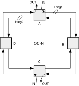
To understand how the UPSR works refer to figure 1 which depicts a four node ring. Each node on this ring is connected to it’s respective adjacent nodes by two fibers, one transmit, and one receive. For purposes of discussion the outer fiber loop is referred to as ring1 and the inner fiber loop is referred to as ring2. In this example a circuit is to be set up between nodes A and C. The input at node A travels clockwise on ring1 and egresses at node C. The input to node C also travels clockwise on ring1. The signal egresses at node A completing the circuit, establishing communications between nodes A and B. Notice that all that is needed for this circuit to be operational is the ring1 fiber unidirectional path.
figure 1.
In this expamle ring1 is the working path. Ring2 will become the protection path as shown in figure 2. Protection is facilitated adding a bridging circuit at the input to the SONET network element. Protection traffic now rides on the ring2 (counter clockwise) fiber path. At the output we implement a selector switch which chooses the signal that comes out of the network element. Selection is made upon SONET path parameters. Path parameters such as AIS (alarm indicator signal), LOP (loss of pointer), LOS (loss of signal), SD (signal degrade). Pathing switching is on an individual path basis. For example if there are 84 VT1.5s provisioned between nodes A and C each of the 84 VTs will be individually switched.
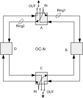
figure 2.
Note that nodes B and D are pass through only
When you have a UPSR think head end bridge, tail end switch. Now assume that this ring is an OC-3 ring and that the tributary traffic is a DS-3 riding in an STS-1. When input traffic from nodes A and C is bridged unto the ring in both the clockwise and counter clockwise directions the time slot is completely used on the ring. Note that nodes B and D are pass throughs. Thus the total amount of traffic a UPSR can support is equal to the ring line rate, N. So if nodes A and C had 3 DS-s provisioned between them then the entire ring bandwidth would be used and no traffic could be added at nodes B and D. Once a node uses a time slot it is no longer available for use by any other node.
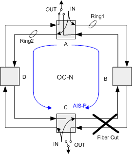
figure 3.
A fiber cut between nodes B and C is shown in figure 3. The blue lines show the traffic from A to C (head end bridge). When the cut happens the receiver on node C ring one detects an OC-N LOS and inserts an AIS-P signal onto all affected paths. When a drop node (in this case node C) detects the AIS-P on the working path the selector performs a a path switch to ring2. Because node C is adjacent to the fiber cut all of its selectors will make a path switch. The output of node C on ring1 has AIS-P on all its path signals except for those added at node C.
Figure 4. shows additional traffic from node B to node A. This is shown in red. In this case node A will not detect the fiber break LOS but the receiver on ring1 will detect the AIS-P that is inserted onto the path at node C. Node A will therefore receive its signal from B on ring2. Node A is not adjacent to the fiber so all of its path selectors will switch based upon path integrity of each individual path independent of the status of any other path.
Therefore each node in a SONET UPSR makes the decision to switch independently without communicating to any of the other nodes. This makes the UPSR particularly easy to provision and manage. When the fiber between B and C is restored the selector at node C will not switch back because the there is not any path degradation to cause the selector to switch. If the selector were to switch back to ring1 the signal would take a hit during the switching interval. Since both ring1 and ring2 signals are good why switch? To be fair there are some user applications that require the user to know on which ring/path the working traffic is on. Because of this vendors have implemented a revertive switching feature that when enabled switches the signal back to the original working path. When a fault occurs the node is allowed 10mS to detect the failure and 50mS to make the switch. This is standard for all SONET systems.
The total restoration time for each path, i.e. the time between when a defect occurs and a protection switch is complete, is the sum of the signal fault detection time + the path AIS
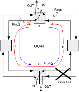
Figure 4.
relay time at non-path terminating nodes + the AIS-P detection time at the path terminating node + the protection switching time at the terminating node. The SONET standards require that the max AIS detection time be 3 frames. In the case of VT signals it is 3 VT superframes. There are 4 STS frames per one VT superframe subsequently it takes longer to detect the VT AIS-V (VT path AIS). This can affect the restoration speed of a large UPSR.